How to create construction lines with XLINE command?

What is a construction line and how to access the XLINE command?

Construction lines or xlines are lines of infinite length that can be created using XLINE command, the following are three ways to access XLINE command:

* When using 2D Drafting workspace, find Home > Draw > XLINE,

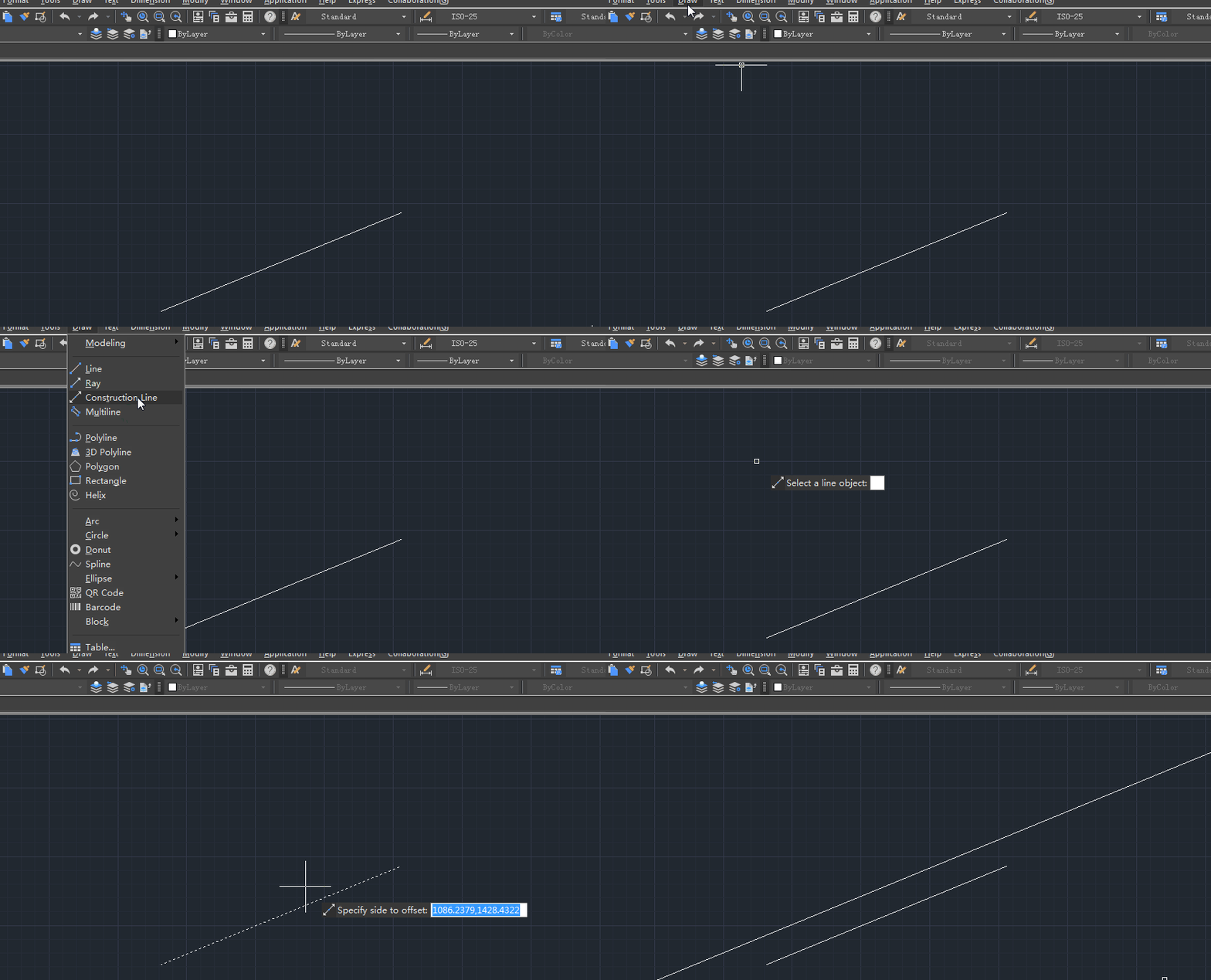
* When using GstarCAD Classic workspace, find Draw > Construction Line,

* Enter “XL” or “XLINE” in the command line, and press Enter key,

Different types of Construction line and how to draw them

When XLINE command is executed, we get the following prompt and we can choose the type of construction line we want to create.

1.Hor: Create a horizontal xline

A horizontal line is parallel to the X axis and passes thought a specified point.

When we have executed XLINE command, just Enter H, and press Enter key,

Then we need to specify through point

2. Ver: Create a vertical xline

A vertical xline is parallel to the Y axis and passes through a specified point.

When we have executed XLINE command, just Enter V, and press Enter key,

Then we need to specify through point,

3. Ang: Create an xline at a specified angle

We can create an xline at a specified angle, which is neither horizontal nor vertical.

There are two ways to specify the angle:

A: specifies the angle at which to place the line.

B: Specifies the angle from a selected reference line

4. Bisect: Create an xline that passes through the selected angle vertex and bisects the angle between the first and second line.

5. Offset: Create an xline parallel to an object

There are two ways to create the parallel xline

A: By specifying the distance the xline is offset from the selected object

Let’s say we want to create an xline pararllel to the following line,

B: By specifying a point that the xline passes through


Discover more from Gstarsoft's Blog

Subscribe to get the latest posts sent to your email.

GstarCAD Blog

www.gstarcad.net

Related Posts

GstarCAD Deep Dive: What Really Happens Inside a CAD Block?

Blocks are everywhere in CAD. A door symbol. A bolt. A valve. A title block. A machine component. At first glance, a block may look like several drawing objects simply…

GstarCAD Deep Dive: How Multiple Top-Level Windows Change Multi-Drawing Workflows

CAD work rarely happens in just one drawing. An engineer may keep a current design open while referring to an earlier revision. A mechanical designer may copy standard details from…

Leave a Reply

Don't Miss out

GstarCAD Deep Dive: What Really Happens Inside a CAD Block?

  • September 29, 2026
GstarCAD Deep Dive: What Really Happens Inside a CAD Block?

GstarCAD Deep Dive: How Multiple Top-Level Windows Change Multi-Drawing Workflows

  • September 23, 2026
GstarCAD Deep Dive: How Multiple Top-Level Windows Change Multi-Drawing Workflows

Gstarsoft and AppliCAD Launch GstarSolutions Thailand, Deepening Their Partnership in the Thai Market

  • September 21, 2026
Gstarsoft and AppliCAD Launch GstarSolutions Thailand, Deepening Their Partnership in the Thai Market

Modernizing Without Disruption: What European SMEs Can Learn from SNIE’s Experience

  • September 18, 2026
Modernizing Without Disruption: What European SMEs Can Learn from SNIE’s Experience

GstarCAD Mechanical 2027: Smarter Workflows, Better Compatibility

  • September 15, 2026
GstarCAD Mechanical 2027: Smarter Workflows, Better Compatibility

AI Rendering Workflow: How GstarRender Improves Design Visualization

  • September 8, 2026
AI Rendering Workflow: How GstarRender Improves Design Visualization

Discover more from Gstarsoft's Blog

Subscribe now to keep reading and get access to the full archive.

Continue reading

Discover more from Gstarsoft's Blog

Subscribe now to keep reading and get access to the full archive.

Continue reading