Polyline is a commonly-used object in CAD drawing. Although it’s simple to use, some experienced designers can’t tell the real differences between line and polyline. Not to mention how confused it would be for new designers. So let’ take a look at it.
Differences between line and polyline
Many newbie designers would ask, with LINE command we could continuously draw multiple lines and with PLINE command we could also continuously draw multiple lines, then what’s the differences between the two of them?
My answer is there are many differences between them. The most obvious one is that with LINE command we draw straight line segments that are separate objects while with PLINE command we draw a polyline that is regarded as one object. We could see this difference by selecting what we draw, as shown in the following picture,

Look at the icon in the toolbar, as shown in the following picture.

we can see that polyline consists of straight line segment as well as arc segment. Hover the cursor over the icon for line and polyline to see the difference in the Command line, as shown in the following picture.


Pay attention to the Command line when using the PLINE and LINE, and we could learn more differences. We can know more about the various parameters of polyline through the following example.
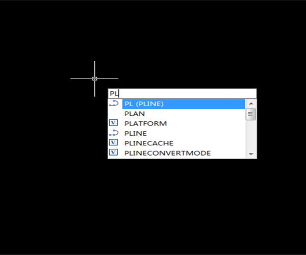
1.Click the polyline button in the toolbar, or enter PL (shortcut for PLINE command) and press Enter, the prompt indicate us to specify start point, enter 0,0 or press Enter to specify the origin of coordinates as start point, or we can select a random point as start point. After specifying the start point, pay attention to the Command line to see the parameters there, as shown in the following picture.

We can see the default option: Specify next point. That is to say that we can draw a line by specifying a point. We can also see more parameters in the square brackets: arc, halfwidth, length, undo,width,angle. The letters in the brackets are keywords for the parameters. Enter the letter and press Enter we can execute corresponding command.
2. Move the cursor horizontally, when polar with dashed lines appears or angle for dynamic input turns 0, enter 10 to draw a 10 length line, as shown in the following picture.

After drawing the line, another parameter Close (C) has appeared in the Command line.
3. Enter A, press Enter to switch to draw arc, let’s see how parameters change, as shown in the following picture.

Parameters Width, Halfwidth and Undo have remained with a series of parameters added. Parameters Angle, Center, Direction, Radius, Second point (Second pt) are used for drawing arc while parameter line is to switch to draw line. Which to use to draw arc depends on the drawing. But I suggest trying every parameter to know their properties and we can choose the most suitable one for our drawing. Please note that radius can be both positive and negative and you can compare the different effect.
4. Move the cursor upward and when it’s in vertical direction enter 10 to create a semicircle. And then move the cursor to continue to draw arc, as shown in the following picture.

There aren’t any changes to the parameter in this status.
5. Enter L and press Enter to switch to draw the line. Enter W, press Enter and the Command line would indicate you to specify starting width, enter 2 and press Enter, the Command line would continue to indicate to specify ending width, press Enter is to use the already enter 2 to be the ending width, as shown in the following picture.

Width is a parameter exclusively owned by polyline, line, cycle, arc, spline ellipse and other objects don’t have width parameter. In many professional versions, the width is used to indicate cables or pipeline. But width is different from the plotted lineweight. Plotted lineweight is not the geometric parameter, so it remains the same regardless of the Plot Scale. For example, if you set it to 0.3 millimeter, it will be 0.3 millimeters when plotted. If there are requirements for the plotted lineweight of polyline, then we have to set the polyline lineweight according to plot scale, if the plot scale is 1:100 and the plotted lineweight is 0.3 millimeter, then we need to set the lineweight of polyline to 100×0.3=30.
Move the cursor horizontally, enter 10 and specify the length of the line segment.
In addition to Width(W), polyline has another parameter Halfwidth that has the same function Width, we can choose either according to known conditions.
Enter H and press Enter, the prompt indicates us to specify starting half-width(We have enter 2 as width, so the default half-width here is 1), enter 3, press Enter, when the prompt indicates us to specify ending half-width, press Enter and we can get an arrow, move the cursor horizontally, enter 10 to drawing an arrow 6 in width and 10 in length, as shown in the following picture.

Press Enter or Space to finish drawing with Polyline
The above is a good example that parameters of Polyline are easy-to-use and you can try the parameters for arc line segment yourself.
Types of special polyline
In addition to PLINE, there are other graphics that belong to polyline, but they are very unique in shape and therefore require different drawing parameters and methods, some of them are Rectangle (REC), Polygon(POL), as shown in the following picture.

When drawing these graphics, please pay attention to the Command line for more parameters, for example, when drawing a rectangle(REC), we can set Fillet, Chamfer, Elevation and so on. The Elevation is the Z-coordinate, so if we just want to create 2D drawings, don’t set the Elevation.
How to create circle polyline
If we want to create a cycle and want to set the line width, we can use DONUT, or we can just create a cycle with POLYLINE command, which is really easy to use.
Enter PL, press Enter and specify a start point, enter A and press Enter to enable arc drawing, move the cursor in the vertical direction, enter 10, press Enter, enter CL, press Enter to close the polyline and we can get a circle polyline, as shown in the following picture.

How to create ellipse polyline
We cannot create an ellipse with Polyline command, so we need to use ELLIPSE command, but before that, we need to set a variable: PELLIPSE.
Enter PELLIPSE, press Enter, enter 1, press Enter to set the ellipse as polyline.
Enter EL, press Enter, move the cursor to specify long axis and minor axis, as shown in the following picture.

After setting the ellipse as polyline, we can set the line width at the Properties Panel.
Summary
The above are tips and tricks for polyline and its parameter. Polyline is commonly-used and CAD provides many editing tools, such as Pinch Edit and Polyline Edit(PE), higher version of CAD also provides Quick Pinch Edit Menu to transform line segment to arc segment and add and delete vertex.
Discover more from Gstarsoft's Blog
Subscribe to get the latest posts sent to your email.


