Firstly, I want to clarify that you don’t have to use LIMITS and many designers are actually not using it anymore. No big deal at all if you don’t know LIMITS when you make your drawings.
This command is from the old version of CAD. In the early version of CAD, the drawing procedure is like this: Firstly, you have to know you’re having an A4 drawing or A3 drawing, and accordingly you need to set the limits for your drawing ( which is the lower left and upper right part of the drawing), grids only appear within the drawing limits, and within the limits we can draw by using snap gird, as shown in the following picture.

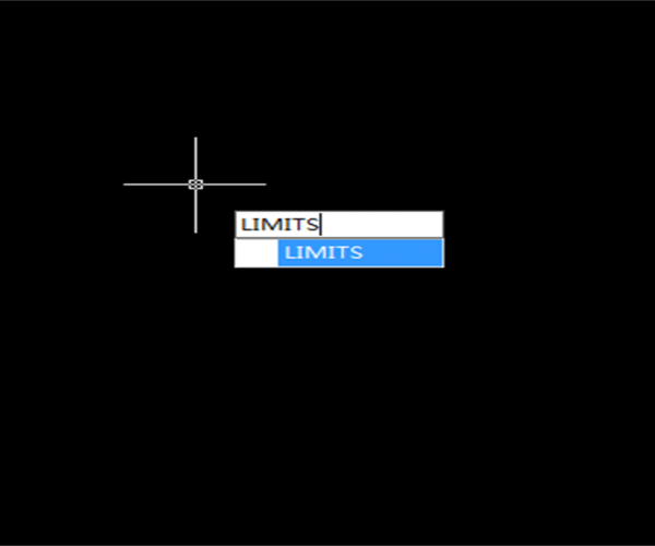
Enter Limits command to set drawing limits for the lower left and upper right corner. If the limcheck is set 1, then we’ll have to draw within the limits. If you can’t draw in your current drawing, you can check if you have set limcheck as 1.
Method to check and modify limcheck: enter limcheck in the command line, press Enter, if the current value is 1, enter 0 and press Enter.
With the increasing performance of CAD software, Limits command is seldom used by users. But later version of CAD still reserved this command and it still plays a part, though very limited, in drawing, zooming and printing.
In your daily drawing, you could just ignore Limits, it really doesn’t matter, but this doesn’t mean you can draw however you like, you’d better drawing near the point of origin; have a good plan before you draw, for example, what size of graphics are you going to draw, text height etc. It will eventually improve your efficiency in drawing, modifying and plotting your drawings.
We can use Limits to set the boundary of your drawing, and ZOOM-All to zoom the whole drawing, so the graphics don’t look too big or small or even beyond the boundary in the default status.
Discover more from Gstarsoft's Blog
Subscribe to get the latest posts sent to your email.


