
In CAD, users can set their own custom shortcuts, for example, CTRL+SHIFT+S is “Save drawing as”. In this post, we will talk more about how to use SHIFT in CAD.
1.Delete objects from Selection Set
When removing certain parts from the selected objects, we can press SHIFT and click or window select the part to be removed.
2. Ortho Mode On/Off
Switching to Ortho Mode with SHIFT Key is more convenient than F8 if designers only need to draw one or two lines.
3. Add objects to selection set ( when cumulative selection is off)
If we have disabled cumulative selection ( set variable PICKADD to 0, check the “Use Shift to add to selection” in the Options dialog box), as shown in the following picture, in order to add the newly-selected objects to the selection set, we need to press SHIFT and select new objects. By default, the cumulative selection is on so we cannot press the SHIFT.

4. Select multiple pinch point to edit
After selecting a certain object, we can perform Stretch, Rotate or Zoom after specifying the pinch point. When selecting the pinch point, we can press SHIFT in order to select more at one time, then we can perform on multiple objects.
5. SHIFT+right-click to open the Object Snap shortcut menu
CAD users usually open several commonly-used snap mode when drawing, when need to switch to other snap modes, we could either enter the shortcut for the snap mode or press SHIFT +RIGHT CLICK TO select from the popped-up menu.
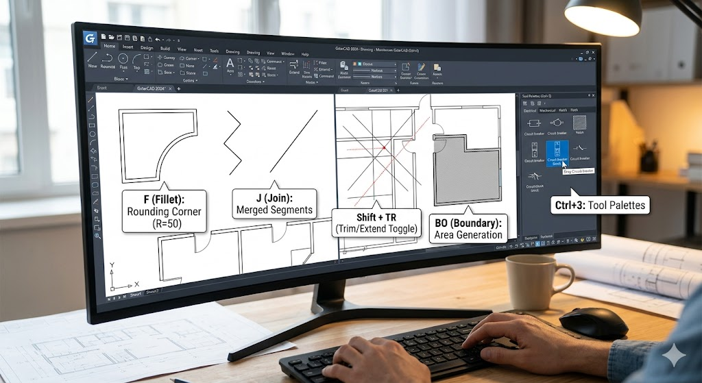
6. Switch between Trim and Extend
Users can press SHIFT to toggle between Trim and Extend commands. For example, if you are using Trim command, press SHIFT will switch to Extend command.
7. Drag with SHIFT and middle mouse button
By default, pressing middle mouse button to drag is the pan of viewport. If users press middle mouse button and SHIFT at the same time, it would be DORBIT; releasing the SHIFT and it resumes to pan, so it’s more convenient when observing 3D objects.
8. Press SHIFT to display tracking vector after turning off automatic display of object snap tracking vector
When we turn on the Object Snap Tracking at the bottom status bar, a small + appears at the point that we specify and when we move the cursor, a tracking vector (feint dashed line) appears, as shown in the following picture.

The SHIFT key may have other users and the above usages may be not applicable anymore to new versions of CAD, I will keep it updated every now and then, thanks for your attention.
Discover more from Gstarsoft's Blog
Subscribe to get the latest posts sent to your email.


