CAD system has different clip commands for different objects: to clip image, the command is IMAGECLIP; to clip viewport, the command is VPCLIP; to clip block and Xref, the command is XCLIP.
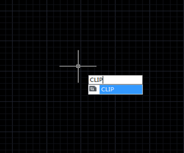
In higher version of CAD system, the CLIP command replaces XCLIP, IMAGECLIP, VPCLIP, etc. It crops a block, Xref, image, viewport and underlay (PDF or DGN) to a specified boundary.
XCLIP
The XCLIP command is used to clip selected external reference or block reference by clipping its specified boundary.
How to access XCLIP:
Menu: Modify > Clip > XCLIP, as shown in the following picture,

Command: XCLIP, as shown in the following picture,

IMAGECLIP
The IMAGECLIP command is used to clip a selected image by specified boundary.
How to access IMAGECLIP
Menu: Modify > Clip > Image, as shown in the following picture,

Command: IMAGECLIP, as shown in the following picture,

VPCLIP
The VPCLIP command is used to clip the object in layout viewport and adjust the viewport frame shape.
How to access VPCLIP
Menu: Modify > Clip < Viewport, as shown in the following picture,

Command: VPCLIP, as shown in the following picture,

Sometimes we need create irregular viewport in the layout space, such as L or circle, we can clip with specified boundary.
For example, open a drawing with graphics objects, them switch to layout space, draw a circle as the clip boundary, as shown in the following picture,

The command line will give the following prompts:
“Select clipping object or [Polygonal ]<Polygonal>”
“Specify start point”
CLIP
In higher version of CAD system, the new CLIP command is a combination of the above commands and the XCLIP, IMAGECLIP and VPCLIP remain. So if your CAD system supports CLIP command, remembering only CLIP command will do.

Discover more from Gstarsoft's Blog
Subscribe to get the latest posts sent to your email.


