In CAD, Object Snap Tracking has more options than displayed in the Setting dialog and there are many ways to set these options, let’s explore more.
Object Snap Tracking is among the most import drawing aids. It can precisely locate objects and users can use the cursor to precisely locate destination points such as the center, endpoint geometric center and perpendicular.
We normally set the Object Snap Tracking in the Setting dialog, as is shown in the following picture.

It’s very easy to understand each OSNAP mode because they provide vivid symbols and there are instructions when you pass the cursor over the mode.
The mode will be active as long as the OSNAP is turned on in the drafting settings dialog. Many users tend to select all, I don’t think this is a good idea since selecting all will increase the calculated amount when snapping and would interfere each other, so I suggest just select commonly-used modes such as endpoint, intersection, midpoint and center.
If we just use the OSNAP occasionally, we can set temporary OSNAP modes and even more modes using other methods. For example:
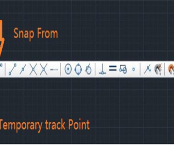
(1) Use OSNAP toolbar, as shown in the following picture.

Turn on the OSNAP toolbar, if we want to temporarily use a specific mode we can click the icon in the toolbar. There are two more modes in the toolbar than in the dialog box: Temporary track point and Snap From, you can also click Snap to None to temporarily cancel all the modes that you selected in the dialog box. The point of temporary snap modes is that they will no longer be active once you use it.
Note: Temporary snap modes only work when locating points, if you didn’t execute any commands and without any prompts indicating you to locate points, then clicking buttons in the OSNAP toolbar won’t work, and it could only prompts Unknown command.
(2) SHIFT + Right-click to pop up shortcut menu, as shown in the following.

Compared with the toolbar, there are three more modes: Mid Between 2 Points, Point Filters and 3D OSNAP. When there is no connecting line between two points, we can use Point Filters to snap the midpoint between the two points. With Point Filters, we can snap a certain coordinate of certain point, for example, we can get X-coordinate of one point and get Y-coordinate of another point. 3D Osnap also has Center of face and Nearest to face in addition to normal modes.
(3) Enter corresponding abbreviation in the Command line
When the Command line prompts indicate us to locate a point and specify the coordinates, we can execute the corresponding mode by entering the mode name or its abbreviation, the following is a list of snap modes and their abbreviations.
Endpoint: abbrv “END”, is used to snap endpoint of objects such as arc or line.
Midpoint: abbrv “MIN”, is used to snap midpoint of object
Intersection: abbrv “INT”, is used to snap points where two objects intersect
Apparent Intersection: abbrv “APP”, is used to snap the intersection of two objects after extended and projected. If the two objects are not directly intersected, the CAD system would calculate the intersection after extension, or the intersection on projected line of different faces.
Extension: abbrv “EXT”, is used to snap a point on the object or on its extension path. In this mode, move the cursor over certain line or arc, there would be a feint dashed line in the same direction of the line or arc and users can select a point on this feint dashed line.
Center: abbrv “CEN”, is used to snap center of circle or arc.
Quadrant: abbrv “QUA”, is used to snap quadrant points of circle or arc. Quadrant points are points of circle that are in the direction of 0°, 90°, 180°, and 270°.
Tangent: abbrv “TAN”, is used to snap point where a line touches the edge of a circle, but does not cross it.
Perpendicular: abbrv “PER”, is used to draw a line from one point to another point at 90 degrees to an object.
Parallel: abbrv “PAR”, is used to snap points on a line that is parallel with the specified line.
Node: abbrv “NOD”, is used to snap objects.
Insert: abbrv “INS”, is used to snap insertions of block, text, attribute , attribute definition and other objects.
Nearest: abbrv “NEA”, is used to snap the closest point to the specified object.
None: abbrv “NON”, is used to disable all snap modes.
From: abbrv “FRO”, can be used together with other snap modes, to snap base point of specified snap mode.
Temporary track point: abbrv “TT”, is used to polar track objects by specifying base point.
Mid of 2 points: abbrv “MTP” or “M2P”, is used to snap the midpoint of two points.
Tracking: abbrv “TK”, can snap one base point, and set the direction and distance of offset, snap a point that is certain distance away from another point. (This snap mode is not available in the toolbar, SHIFT+Right-click, we can only enter the mode name to execute them.
Discover more from Gstarsoft's Blog
Subscribe to get the latest posts sent to your email.