Have you ever wanted to dimension a series of circles or arcs using one command? QDIM is that one command that creates a series of baseline or continued dimensions or dimensions a series of circles and arcs, which greatly improves the drawing efficiency.
Where to find and how to use QDIM
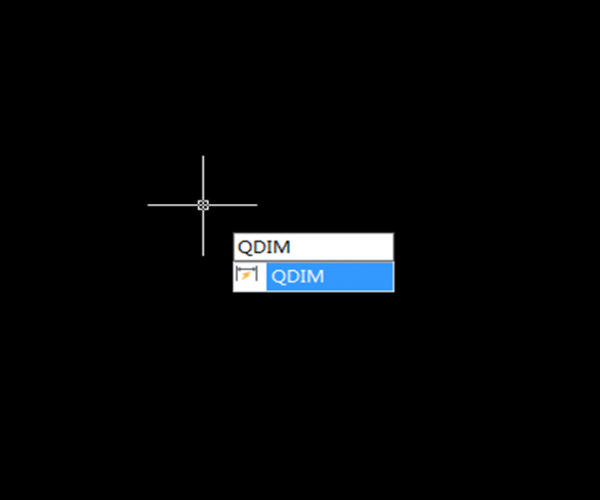
- Enter QDIM, and press Enter key,
Or Find Dimension > Quick Dimension in the menu, as shown in the following picture,

2. Select the geometry to dimension and press Enter key
3. Specify dimension line position, or [Continuous/Staggered/Baseline/Ordinate/Radius/Diameter/datumPoint/Edit/seTtings], as shown in the following picture, then press Enter key,

4. Then specify dimension line position
5. Users can always use ESC to interrupt the command.
The use of QDIM in creating different types of dimensions
- Continuous
Creates a series of continued dimensions, as shown in the following picture,

2. Staggered
Creates a series of staggered dimensions, as shown in the following picture,

3. Baseline
Creates a series of baseline dimensions where linear dimensions share a common extension line, as shown in the following picture,

4. Ordinate
Creates a series of ordinate dimension, as shown in the following picture,

5. Radius
Creates a series of radial dimensions, as shown in the following picture,

6. Diameter
Creates a series of diameter dimensions, as shown in the following picture,

7. Datum point
Sets a new datum point for baseline and ordinate dimensions. After specifying new datum point as prompted to, we’ll go back to the last prompt.
8. Edit
Enable changes to a series of dimension points, including adding or deleting dimension points, as shown in the following picture,

Discover more from Gstarsoft's Blog
Subscribe to get the latest posts sent to your email.


