The definition of attribute blocks is simple: just make your drawing, then define the attribute text and select the definitions and make them blocks, the following has introduced the definition using axis number — which is a pretty simple attribute block.
1.Draw the internal graphics of the block, for axis number that should be a circle, now we draw a circle whose radius is 5, as shown in the following picture,

2. As shown in the following picture, select Draw > Block > Define Attributes… as shown in the following picture,

or enter ATTDEF to pop up the Attribute Definition dialog box, as shown in the following picture,

Although there are many parameters in the dialog box, but there are only three that we need to know what they are used for, which are Tag, Prompt and Default.
Tag: identifies each occurrence of an attribute in the drawing. Enter the attribute tag using any combination of automatically changed to uppercase.
Prompt: Specifies the prompt that is displayed when you insert a block containing this attribute definition. If you do not enter a prompt, the attribute tag is used as a prompt. If you select Constant in the Model area, the Prompt option is not available.
Default: Specifies the default attribute value.
Set the justification of text as Center and Text style as Standard, we can ignore other parameters at the moment, as shown in the following picture,

Click OK to close the dialog box, put the attribute text into the center of the circle, as shown in the following picture,

Because we have chosen Center as the justification, after specifying the center of the circle, the attribute text would be at the center of the circle, as shown in the following picture and it displays the tag of the attribute instead of value,

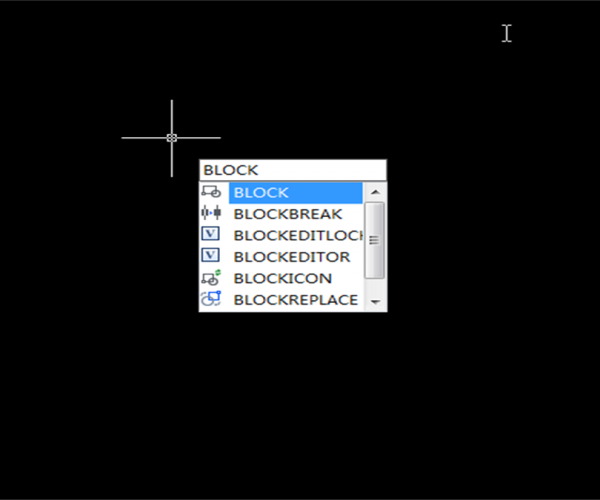
Select the circle and attribute text altogether, enter B, press Enter to open the “Block Definition” dialog box, we can name the block as AXISNO and specify the enter point or quadrantal point below as the pick point, as shown in the following picture,

Click OK to close the Block Definition dialog box, and a new dialog box “Edit Attribute” would pop up, the Prompt and Default that we set before would display in this dialog box and we can also see that the Tag in the block has turned to default, as shown in the following picture,

Just close the “Edit Attribute” dialog box and use the default value, the attribute block that we defined is shown in the following picture.

Enter “I” to open the “Insert” dialog box, choose the AXISNO we just defined, click OK to close the dialog box, as shown in the following picture,

then put the Insertion point on the right of the original block, the “Edit Attribute dialog box would pop up, as shown in the following picture,

Enter 2 and press Enter to set the attribute value to 2, as shown in the following picture,


Double-click either of the blocks, and the Enhanced Attribute Editor would pop up, we can change the attribute value as we need, as shown in the following picture,

Join our discord community!
Connect with CAD experts, share technical insights, and get real-time support from the global community.
Join Discord ServerShare & Get a $10 Amazon Gift Card
Share your honest GstarCAD feedback and get a chance to win a $10 Amazon gift card.
Write a ReviewDiscover more from Gstarsoft's Blog
Subscribe to get the latest posts sent to your email.


