Basics about CAD layers tutorial 2

* layer 0

Layer 0 is the default layer of every drawing, which could not be deleted. There are some special properties of layer 0. Please see another blog post to review the differences between layer 0 and other layers.

* Layer Defpoints

Some users have noticed the layer Defpoints because this special layer often comes from nowhere and users who know it will take advantage of its special properties while others who don’t know its properties will cause problems by putting objects on it.

The CAD system will automatically create Defpoints layer as long as you creates dimensions — this layer is used to place definition points of dimensions. Well, you may be asking what a definition point is. A definition point are several key points of dimension that are used to define and adjust dimensions. When we turn on the node option in the Object Snap, the nodes of dimensions that we snap are actually those definition points.

What makes Defpoints layer unique is not that it’s created automatically by CAD system but that this layer is set not to be plotted and we can’t change this setup.

If we accidentally place geometric objects on this layer, those objects will literally disappear when you plot the drawing. Some users therefore put objects that they don’t need to plot such as viewport boundary on this layer.

* Layer Filter

Layer Filter is a very useful tool and we can use it to find layers that meet our criteria.

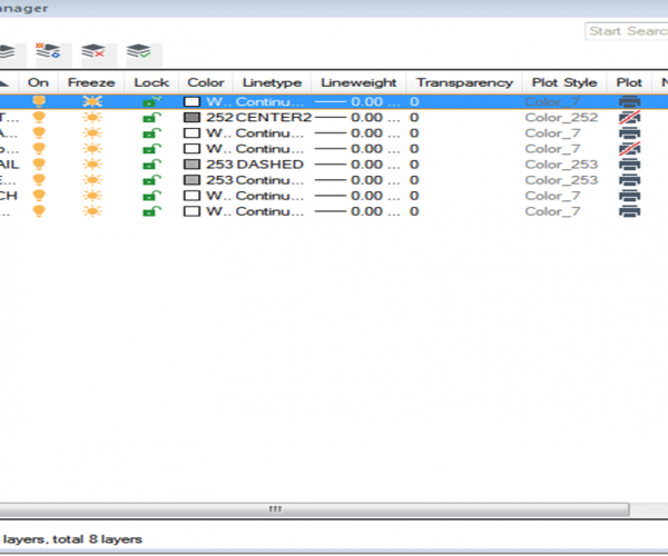
Open the Layer Properties Manager, and click the New Property Filter, a window will pop up, as shown in the following picture,

* Layer States Manager

Sometimes we need to repeatedly turn on/off/lock/unlock layers, we can save those layer states and when we need to use them, just restore them. CAD also provides Layer Previous to undo the last change or a set of changes made to the layer settings, as shown in the following picture,

Join our discord community!

Connect with CAD experts, share technical insights, and get real-time support from the global community.

Join Discord Server

Discover more from Gstarsoft's Blog

Subscribe to get the latest posts sent to your email.

GstarCAD Blog

www.gstarcad.net

Related Posts

Common Methods for Inserting Images in GstarCAD

In professional CAD workflows, integrating raster images—such as site maps, reference sketches, or interior renders—is essential for visualization and project coordination. However, choosing the wrong insertion method can lead to…

The Ultimate Guide to GstarCAD Mechanical 2026: The Future of Manufacturing Design

GstarCAD Mechanical 2026 drafting/design software, covers all fields of mechanical design. Join our discord community! Connect with CAD experts, share technical insights, and get real-time support from the global community.…

Leave a Reply

Don't Miss out

Common Methods for Inserting Images in GstarCAD

  • May 22, 2026
Common Methods for Inserting Images in GstarCAD

Building the Future of Steel: How Tarkon Optimizes Structural Design with GstarCAD

  • May 7, 2026
Building the Future of Steel: How Tarkon Optimizes Structural Design with GstarCAD

GstarCAD 2026: Is It Time to Look Beyond the AutoCAD Legacy?

  • April 21, 2026
GstarCAD 2026: Is It Time to Look Beyond the AutoCAD Legacy?

Gstarsoft Showcases Integrated CAD + BIM Solutions at BIM World Paris 2026

  • April 3, 2026
Gstarsoft Showcases Integrated CAD + BIM Solutions at BIM World Paris 2026

Boost CAD Productivity with GstarCAD 2026’s XTP Import Feature

  • March 24, 2026
Boost CAD Productivity with GstarCAD 2026’s XTP Import Feature

Case study: How TopenTech Optimized Equipment Diagnostics and Field Productivity with GstarCAD

  • March 9, 2026
Case study: How TopenTech Optimized Equipment Diagnostics and Field Productivity with GstarCAD

Discover more from Gstarsoft's Blog

Subscribe now to keep reading and get access to the full archive.

Continue reading

Discover more from Gstarsoft's Blog

Subscribe now to keep reading and get access to the full archive.

Continue reading