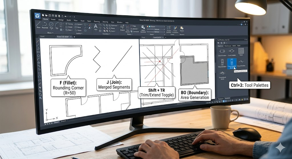
In the process of drawing and editing with GstarCAD, mastering basic functions and shortcuts can significantly reduce redundant operations while improving drawing precision and efficiency. The five features—Ctrl+3 (Tool Palettes), F (Fillet/Chamfer), J (Join), Trim/Extend Toggle, and BO (Boundary)—are high-frequency tools used by designers daily. As a benchmark for domestic CAD software, GstarCAD has optimized these functions for better convenience and compatibility. Below is a detailed breakdown of how to use these features, their operation steps, and applicable scenarios to help designers get started quickly.
Ctrl+3: Tool Palettes for Efficient Resource Management
Ctrl+3 is the shortcut for calling the Tool Palettes in GstarCAD. The Tool Palettes integrate resources such as blocks and hatch patterns, eliminating the need to search through menu bars. It is particularly useful for scenarios involving frequent use of specific drawing elements, saving time and enhancing drawing continuity.
Usage Tips and Steps:
Open your drawing file in GstarCAD. Press [Ctrl+3] to quickly display the Tool Palettes (it defaults to the right side of the interface; you can drag the border to adjust its position and size to fit your habits).
The palettes contain multiple category tabs, such as “Electrical,” “Mechanical,” and “Hatch.” Click the corresponding tab to switch to the required resource interface.
To use a resource, simply click the block or pattern in the palette to apply it directly to your drawing.
To close: Press [Ctrl+3] again to quickly hide the Tool Palettes, or click the “X” button in the top-right corner of the palette.
F (Fillet): Multi-Scenario Graphic Connection
The Fillet command (shortcut: F) is used for rounding corners of intersecting or non-intersecting line segments and arcs, or for quickly connecting lines. Its concise operation and adjustable parameters make it an essential tool for refining graphic details.
Usage Tips and Steps:
Rounding corners: Enter [F] and press Enter. Enter [R] to set the radius. Then, click the two line segments you wish to fillet.
Quick connection: To connect two non-intersecting line segments, enter [F] and press Enter. Simply click the two segments sequentially. Without setting a distance or radius, the software will automatically connect them into a single entity.
J (Join): Consolidating Dispersed Objects
The Join command (shortcut: J) merges collinear or connected line segments, arcs, or polylines into a single object. It is ideal for repairing fragmented graphics, consolidating lines, and converting arc segments, helping to keep drawings clean and efficient.
Usage Tips and Steps:
Basic joining: Select multiple segments that are end-to-end or collinear. Enter [J] and press Enter. Select all objects to be joined (or press Enter if already selected) to merge them into one.
Restoring Arcs/Elliptical Arcs: Select an arc or elliptical arc, enter [J], and press Enter. When prompted for “Close (L),” enter [L] to convert it into a complete circle or ellipse.
Fuzzy Joining: To join non-continuous but collinear segments, select them and enter [J]. If there are gaps, enter [F] (Fuzzy distance) to set an appropriate tolerance value, allowing the software to bridge the gaps and merge the lines.
Trim/Extend Toggle: Efficient Detail Optimization
GstarCAD allows for a quick toggle between Trim and Extend operations, which is highly efficient for complex drawings, reducing the need to switch commands repeatedly.
Usage Tips and Steps:
Enter [TRIM] (shortcut: TR) and press Enter. Click the lines you wish to trim to delete them while keeping the boundaries intact.
Switching: Without exiting the command, hold down the [Shift] key. The cursor will change to an “Extend” icon. Click the line segment you wish to extend to the boundary. Release the Shift key to return to Trim mode.
BO (Boundary): Quick Generation for Calculation and Hatching
The Boundary command (shortcut: BO) quickly identifies closed areas formed by lines, arcs, or polygons to generate regions or polylines. It is widely used for area calculations, hatching, and editing, eliminating the need to manually draw boundaries.
Usage Tips and Steps:
Ensure the closed area is formed by continuous objects with no gaps or breaks. Enter [BO] and press Enter to open the “Boundary Creation” dialog box.
Parameter settings: Choose the object type to be generated (Region or Polyline).
Extraction: Click “Pick Points,” return to the drawing area, and click inside the closed region. The software will automatically detect the boundary.
Confirmation: Press Enter after picking the points, then click “OK” in the dialog box to generate the boundary, which can now be used for hatching or area measurement.
Join our discord community!
Connect with CAD experts, share technical insights, and get real-time support from the global community.
Join Discord ServerShare Your Experience
Are you using GstarCAD? Share your honest feedback on G2; it truly helps us improve and grow!
Write a Review on G2Discover more from Gstarsoft's Blog
Subscribe to get the latest posts sent to your email.