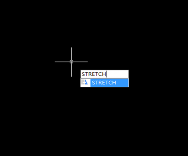
The Stretch command is a simple and special command: on one hand, it’s as simple and easy-to-operate as the Move command, on the other hand, it has different ways from other commands in selecting objects. Why is that?
When using other commands, we need to either select the whole object such as the commands of Move, Rotate, Copy, Mirror, Zoom, or click on the part that we want to edit such as the command of Extend, Trim, Lengthen and so on. We can not only use the stretch command to select the whole object, but also select part of the object. We need to execute the Stretch command before selecting the object using lower version of CAD, but now we can first select the object and then execute the command with any CAD version.
With Stretch command, only the selected vertexes of the object will be moved
We can use the Stretch command if we only want to adjust the dimension of an object in certain direction and please pay attention to the following when selecting objects:
Select the vertexes to be moved from right to left, as shown in the following picture.

After the selection, the whole object becomes semi-transparent and we can’t see the selected points but we can see which points follow the cursor after specifying the base point, as shown in the following picture.

After selecting the object or vertex, press Enter to confirm the action. And the Stretch command has the same options as the Move command: base point, the second point, and Displacement. We can refer to the Move command when using the stretch command.
Attention: Some 2D graphics can’t be stretched, such as cycle, ellipse and other graphics that are unable to change their forms, if you select a quadrantal point of a cycle and an ellipse with a selection window, Stretch won’t make them move, if you window select three quadrantal points, they’ll move when stretched.
If selected as a whole, the object will actually move
If selected as a whole by using a point,selection window, group and so on, it equals that all vertexes will be stretched and the whole object will actually move.

Pay attention when you have multiple window selection with Stretch command
With the Stretch command, we can window select multiple vertexes of different objects, but we can’t window select multiple vertexes of the same object.
We could either window select the vertexes of different objects at a time or at several times.
After the Stretch command, as shown in the following.

When we want to add other vertexes after having window selected some vertexes of an object, we’ll find that it just doesn’t work and the vertexes you want to add won’t either be added or replace the previous vertexes. For example, we have window selected the three right vertexes of the hexagon, and then we continue to window select a left vertex of the hexagon.
Stretch the object after specify the base point and we can see only the first three vertexes moved while the last selected vertex remained.

If we need to change an object vertically and horizontally, we’ll have to use Stretch command twice: first, select the left and right vertexes to horizontally stretch the object and then select the upper and lower vertexes to vertically stretch the object.
The characteristics of the Stretch command when selecting objects tend to confuse newbies, so let me make a conclusion about when the object will be move and when the object will be stretched:
Only the selected vertexes will be moved; if an object is selected, then all its vertexes are selected; In one operation of the Stretch command, we can’t select multiple vertexes of the same object with window selection.
Join our discord community!
Connect with CAD experts, share technical insights, and get real-time support from the global community.
Join Discord ServerShare & Get a $10 Amazon Gift Card
Share your honest GstarCAD feedback and get a chance to win a $10 Amazon gift card.
Write a ReviewDiscover more from Gstarsoft's Blog
Subscribe to get the latest posts sent to your email.


