In our daily drawing with CAD, we usually need to insert some special characters into the drawing and therefore blocks and block attributes are needed to complete the drawing. A good command of blocks and block attributes can improve the efficiency of drawing as well as the quality of the drawing and can be important in completing complex drawings.
- Characteristics of block in CAD
A block is a combined unit of graphic entities that can have their own layers, linetype, color and other characteristics. Block is treated as a separate and complete object in CAD drawing and users can insert blocks in a specified position according to a certain scale and angle.
Since block is inserted as an entity, CAD system will only keep the overall characteristic parameters instead of the characteristic parameters of every entity in the block. So using blocks when completing complex drawings can greatly save our storage space.
Modifying blocks can also be convenient. If we have modified or update a defined block, then all current drawings that have already inserted this block will be automatically updated.
2. Create blocks
Having said much about the characteristics and advantages of using blocks, you might be asking about how to create blocks, the following are ways to create blocks.
Menu: Draw> block > make…
Tools: Block Editor> enter the name of the block that you want to create
Command: BLOCK(display Block Definition dialog box), -Block (display command line prompts) shortcut: B
Blocks created by using BLOCK command is called internal blocks and they are saved together with drawing files that define them. So internal blocks are saved in the drawing files and they are normally accessed in the drawing files.
After executing the BLOCK command, [Block Definition] dialog box is opened and we can create blocks through this dialog box.

The following is a list of all the items in the dialog box.
• Name: The name of your block can contain at most 255 characters, letters, numbers, spaces and Chinese characters included.
• Base point: is used to specify the base point of inserting your block, if the base point is not specified, the origin of coordinates will be set as base point by default.
• Objects: Click on the Select Objects button to select the block that you want to define. There are three options under Objects bar:
- Retain: Retain the source objects after creating blocks. Not to change any parameters of the source objects that you are defining.
- Convert to block: The source objects will be converted to blocks after creating blocks.
- Delete: The source objects will be deleted after creating the blocks.
• Settings: The meanings of the options under it are as follows:
- Block unit: Specify the unit of your inserted blocks, normally used unit is millimeter, but we can use other units.
- Hyperlink: Click on this button to open Insert Hyperlink dialog box to set a hyperlink for the block that you define.
Behavior: is to specify the behaviors of blocks and there are four options under it.
A. Annotative: is to create annotative block reference. Annotative block reference and attribute support the current annotation scale when inserting them.
B. Match block orientation to layout: To specify the orientation of the block reference in the drawing space viewport match the orientation of the layout. If the Annotative option is unchecked, then the option is not available.
C. Scale uniformly: This is to make sure if the blocks zoom in and out according to a certain scale. If the Annotative option is unchecked, then the option is not available.
D. Allow exploding: This is to make sure if the Explode command is available to explode blocks.
• Description: is used to add additional descriptive information to the blocks.
• Open in block editor: is used to confirm whether to open blocks in block editor in order to edit them after creating the blocks.
3. Write blocks (to save them as separate files)
Command line: WBLOCK shortcut: W
After executing WBLOCK command, the CAD system will open Write Block dialog box. Using this dialog box we can save defined block or selected objects on disc as files.

The blocks created using BLOCK command is saved as a separate file and it can be used by any graphic files.
The meanings of options under Write Block dialog box is as follows:
- Source: is used to select objects when creating blocks. Check Block to select a already defined block in the drop-down list. Check Entire drawing to save all the graphics in the drawing area as blocks. Check Objects to save the graphic objects selected by users as blocks.
- Base point: same as the Block definition dialog box.
- Objects:same as the Block definition dialog box.
- File name and path: is used to specify the name and the saving path
4. Export block
Click File > Export, and choose the file type as block. This will save the whole graphics as block file, and we can also save the defined blocks as separate block files.
5. Nested block
Nested block is a block that contains other blocks, for example, we can insert assembly drawing of a mechanical part as a block, this mechanical part includes rack, support and fastener, and the fastener is also a block that contains screw, gasket and nut. As shown in the following picture.

6. Attribute blocks
Attribute is label or mark that attaches data to the block. Attribute may contain data including part number, price, annotation, name of the owner and so on. The design organization usually use attribute blocks to define the title panel and sign bar of the drawing frame. We can use the same drawing frame but different name, scale and other attributes according to different drawings.
Attribute text needs to be defined first, and the graphics and the attributes being selected together when defining blocks makes the blocks attribute blocks.
The attributes can also be invisible. If the attributes are invisible, they are unavailable for displaying and printing but the attribute information is stored in the graphic files and can be written into extracting files for the database system to use.
7. Anonymous blocks
If we select blocks generated from further development of the software, we can see there is * before the block name in the Properties panel (CTRL+1). We cannot find these blocks in the list when inserting block. We cannot edit anonymous blocks using refedit and block editor since they are only be exploded in order to be edited. Things can be even tricky if we are faced with anonymous block plus multiple insert block, because we can neither explode them nor edit them.
8. Insert blocks
Menu: Insert > Block
Ribbon Insert > Block > Insert
Command: INSERT shortcut: I
With INSERT command, we can insert a single block at a time and we can set parameters of the blocks such as the insertion point, scale and rotation.
After executing INSERT command, CAD system will open Insert dialog box, and we can insert blocks into the drawing area by setting the dialog box.

The meanings of the options in the Insert dialog box are as follows:
- Name: We can select the defined block name in the current drawing from the list, or we can insert block files by clicking the Browse button.
- Path: Show the path of the inserted block.
- Insertion point: The Specify On-screen is checked by default and users can directly insert the absolute position of the coordinates.
- Scale: The Specify On-screen is checked by default, which means when inserting blocks we can also input scale in the Command line. Users can specify scale in different directions by inputting X, Y, Z values. The scale can apply to the whole block if the Uniform Scale is checked.
- Rotation: The Specify On-screen is checked by default, which means when inserting blocks we can input the rotation angle or input the rotation angle in the Angle text box.
- Explode: If this option is checked, the inserted block will be exploded.
9. Block definition and block reference
After defining blocks, a block definition remains in the drawing and even if all the blocks in the drawing are deleted, we can still find those blocks in the Insert dialog box if we input I command. Those inserted blocks in the drawing are called block reference, which means that block definition is referred for once.
Block reference can be deleted while block definition can only be purged (PU) after all the block references in the drawing are purged.
10. Multiple blocks
Command line: MINSERT
Executing the MINSERT command is to insert blocks in the form of rectangular array and this is actually the combination of INSERT and ARRAY command.
Note: the multiple blocks inserted using MINSERT command is regarded as one object.
The multiple blocks cannot be directly exploded, so we need to modify the row and column to 1 in order to change them into normal blocks so they can be exploded.
11. Refedit
Refedit is to edit block definition and therefore make changes to all the block references by editing certain block reference of the block. Remember to save or exit the refedit, or you’ll remain on the refedit status and therefore unable to do many other operations. Refclose is command you can use to exit the refedit, or you can open the refedit toolbar and click the Save button.
12. bedit and Dynamic Block
Bedit function is to make graphic editions to the blocks and set visibility, set behavior and parameters, combining multiple blocks to one block or make the block move to realize parameterization, that is dynamic block. Both the dynamic block and bedit are available, but double-click will lead us to bedit function.
13. Enhanced Attribute Editor
If the block is attribute block, double-click will pop up an enhanced attribute editor and we can directly modify the attributes of the block. If we are going to edit the graphics of attribute blocks, we’ll need the toolbar or command since double-click won’t work.
14. Rename
The block name in one drawing is unique, if two drawings have blocks with same name but different definition and you are going to copy one to another drawing, then you can only have one of the two blocks, but if you want to have them all, you’ll need to rename either of them. The command for this is: Rename, or you can simply input ren.
15. XCLIP
XCLIP command can remove the drawing boundaries or the area outside the boundaries using closed boundaries. It’s very convenient especially when we need to clip complex graphics.
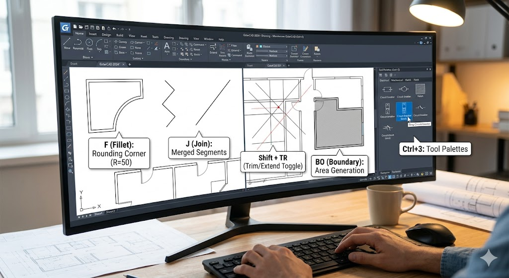
16. Inserting blocks using Tool Palettes
Tool Palettes is a window area that provides an effective method to organize, share and place blocks, pattern filling, and other tools. In the Tool Palettes, there are also custom tools developed by a third-party developer.
Click Tools > Palettes > Tool Palettes or use shortcut CTRL+3 to open the Tool Palettes.
17. Use Design Center to insert block
Users can access other graphics and hatch graphics, block and patterns in the Design Center and they can be dragged to the Tool Palettes. The source graphics can be located in users’ computer, Internet or websites. What’s more, if multiple graphics have been opened, we can switch between different graphics via Design Center (such as layer definition, layout and text style ) to simplify the drawing process.
18. Insert blocks from other files
Open established blocks or graphic files and select parts or the whole graphics. Execute CUT or COPY command, open the destination files to execute PASTE command.
Or use the Design Center to browse other files and insert unfolded blocks directly at the Design Center.
19. Insert blocks using POINT command
Execute DIVIDE or MEASURE command can insert custom internal blocks in the current drawing.
Blocks are extensively used in design and above are the concepts and operations that I have to share, if you want to share yours, please don’t hesitate, just leave a comment or throw me an email.
Discover more from Gstarsoft's Blog
Subscribe to get the latest posts sent to your email.


